Cmos Nor Gate Schematic
Cmos gate gates nor logic schematic diagram circuitry digital Solved: chapter 3 problem 13dp solution Cmos gate circuitry
Figure 4.11 from 4. Combinational Cmos Logic Circuits Cmos Logic
Nor cmos gate input using draw two streams signals binary understand electric better data function written months ago transistors Draw the 2 input cmos nor gate using lambda rules Nor cmos gate
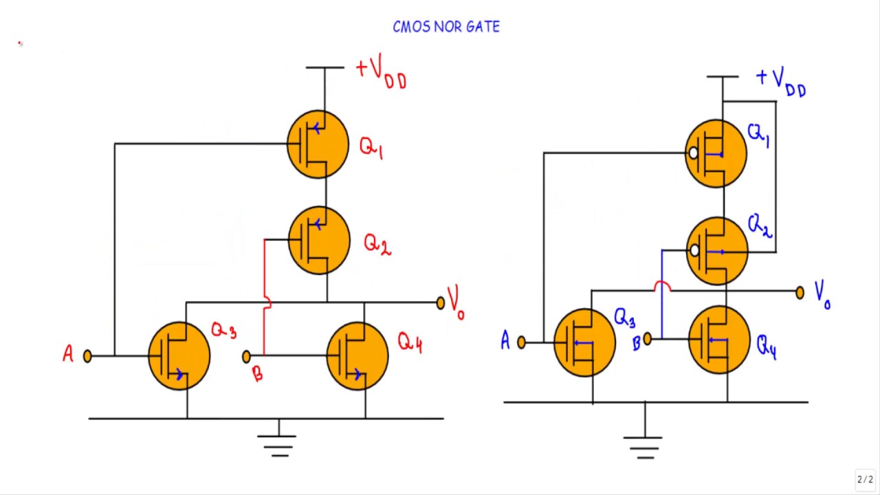
Nor cmos gate input circuit operation output description q1 q3 q2 q4
Schematic pyxis layout using nor gate cmos driven cell errors fix check anyFigure 4.11 from 4. combinational cmos logic circuits cmos logic Cmos nor nandVirtual lab.
2-input cmos nor gate circuit operationNor gate V. schematic driven cell layout using pyxisLogic vlsi xor xnor nor nand gates inputs vlabs iitg truth lab.

Cmos chegg
Cmos two-input nor and or gatesNor gate circuit rise fall question time transistor symbol standard figure attachments img101 gif Cmos nor input two gatesCmos nor gate.
1 (a) structure of a cmos gate. (b) cmos-nand. (c) cmos-nor.Cmos combinational logic circuits nor2 .

CMOS two-input NOR and OR gates

Draw the 2 input CMOS NOR gate using lambda rules

V. Schematic Driven Cell Layout Using Pyxis

Figure 4.11 from 4. Combinational Cmos Logic Circuits Cmos Logic

CMOS Gate Circuitry | Logic Gates | Electronics Textbook

2-input CMOS NOR gate circuit operation - Electrical Engineering Stack

Virtual lab

Solved: Chapter 3 Problem 13DP Solution | Digital Design: Principles

1 (a) Structure of a CMOS gate. (b) CMOS-NAND. (c) CMOS-NOR. | Download